Automated Gear Tester:
MoldedGear LLC engineering team has an average of 25 years of experience in the electrical, mechanical, and machine design fields. Our engineering and design team’s creative talent to design equipment will put your company ahead of the competition. Our team of engineers works closely with our customers, identifies customers’ needs and finds solution for the problems they are encountering.
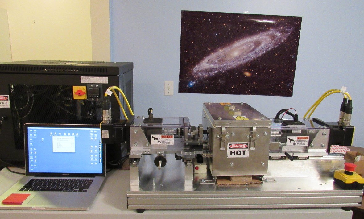
The TEST-PRO Automated Gear Tester Rig, Test-Pro –2017 I & II automated gear testers, distributed by MoldedGear LLC are the most reliable and most advanced plastic/metal gear tester systems in the market.
Automated Gear Tester Specification:
- The test rig is able to measure parallel axis spur, helical or right-hand worm or bevel gear pair, and also gearboxes.
- The test rig is able to test plastic, powder metal, metal gear pars, or these gear materials combinations.
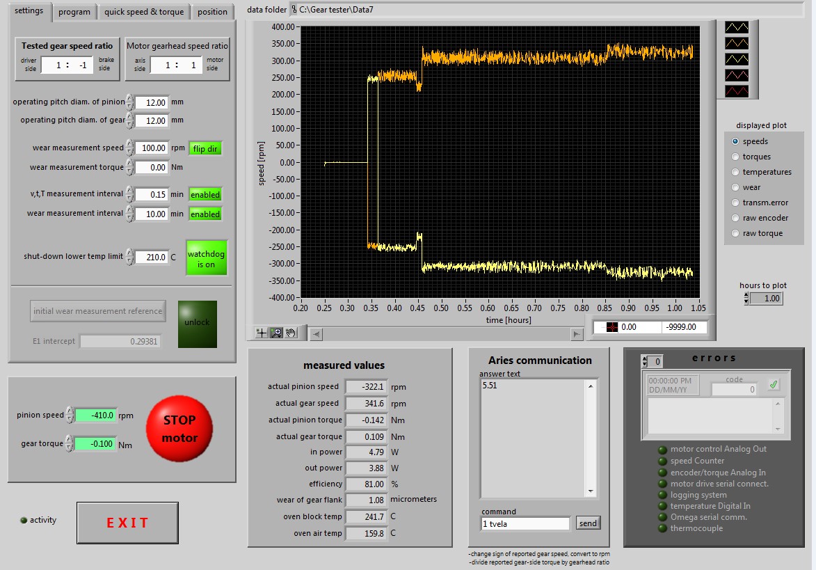
- Computer controlled and monitored (LabVIEW test specific written software supplied).
- Automated gear tribology tester monitors and records cycles, temperature, backlash, continuous gear flank wear, torque and speeds. It is able to determine coefficient of friction between gear mesh.
- The software provides different type of plot vs. time charts. It is possible to plot input, output speed, torque, gear mesh or gearbox efficiency, tooth and single flank test of gear or T.E. Transmission error, which can be used for gear noise related analysis, too.
- The independent "GT calibrator" program provides means to measure the friction torque and also gives the operator the opportunity to update the sensitivity of the torque transducer.
- Driver motor provides speeds up to 5,000 rpm, tester runs in either direction.
- Power up to maximum 1 HP (746 Watt).
- Brake maximum 1HP, max. Constant 40 Nm or more torque.
- Handles parallel or right angle 90 degree shaft gear pairs with a center-to-center distance between 10-70 mm.
- Driver motor and transmission table is able to perform directional adjustment fine adjustment in X-Y horizontal plane, Y direction.
- Motor Break and transmission table is able to take X directional adjustment. Fine adjustment in X-Y horizontal plane, X +/- direction.
- Control system programmable to setup the load spectra, motor speed and break torque in repeated or programmable load cycles.
- Control system capable to setup reverse back drive system and testing, when the break side would be driver.
- All data stored, easy use in commercial presentation packages (excel file preferred).
- Automated Gear Tester is able to stop testing and record number of cycles.
- Gear Tester is equipped with emergency shut down bottoms.
- Center distance setup had digital visual recording.
- Optional Oven: Temperature up to 84°C (183°F)/360 W